


How to Avoid an Out of Spec Angle Bend in Sheet Metal
A bend that is off by one degree usually does not look dramatic.
It just refuses to fit.
The bracket rocks. The flange misses the mating hole. The enclosure door rubs. The welded frame pulls out of square. Then everyone starts pointing at the press brake, the operator, the drawing, the material supplier, or the poor person who made the flat pattern.
We have seen this movie before.
An out-of-spec angle bend in sheet metal is rarely caused by one mistake. It is usually the result of several small assumptions stacking up: material thickness, grain direction, tooling, bend radius, k-factor, springback, and inspection method. Ignore one, and you may get lucky. Ignore three, and you are buying scrap.
What Is an Out-of-Spec Angle Bend?
An out-of-spec angle bend happens when the finished bend angle falls outside the allowed tolerance on the drawing, purchase spec, or agreed inspection standard.
Simple enough.
But the cause is not always simple. A 90° bend may come off the brake at 90.5°, relax to 91.2° after springback, shift again after welding, and look worse after powder coating because the mating edge is now tighter than expected.
That is why good sheet metal bending is not just “push metal into a V-die and hope.” It is controlled forming.
And control starts with the print.
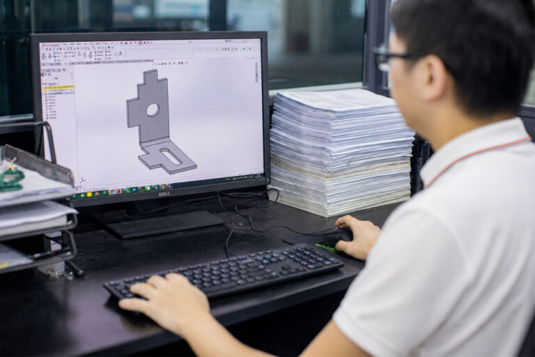
Start With the Drawing: Define “Good” Before the Metal Moves
A vague drawing is expensive.
If the print says “bend 90°” but does not define angle tolerance, inside radius, datum scheme, flange length, material grade, grain direction, or inspection method, the shop has to infer too much. That may work for a rough bracket. It does not work for tight enclosures, electronics chassis, aerospace hardware, medical carts, or parts that join a welded frame.
Before releasing custom sheet metal parts, check that the drawing answers these questions:
- What is the nominal bend angle?
- What is the allowed angular tolerance?
- Is the tolerance measured free-state or after assembly?
- What is the inside bend radius?
- Is the radius cosmetic, functional, or both?
- Is the bend parallel or transverse to grain?
- Which surface is the cosmetic side?
- Are there bend reliefs near notches, slots, or tabs?
- What datum controls the flange?
- Is the part inspected with a protractor, CMM, fixture, optical comparator, or go/no-go gauge?
This is where many shops lose time. The brake operator can form a beautiful part and still miss the buyer’s intent if the design package is thin.
Why Sheet Metal Bends Go Out of Spec
There are five repeat offenders.
1. Material Thickness Is Not Always the Number in CAD
CAD says 1.5 mm. The coil says something close to 1.5 mm. Reality says “measure me.”
Sheet thickness variation changes bend allowance, punch penetration, springback, and flange position. The effect is worse when the tolerance is tight or when small flanges leave little room for correction.
We like to verify actual thickness before dialing in a job. Not theoretical thickness. Actual thickness.
2. Grain Direction Changes Bend Behavior
Rolled sheet has grain from the mill rolling process. Bend with the grain and the material usually forms with less force — but cracking risk can rise on the outside radius. Bend across the grain and you often get better crack resistance, though the forming load may increase.
This matters most with harder materials, tight radii, stainless steels, aluminum tempers, and parts with cosmetic faces.
A good rule: call out grain direction when it affects function, strength, or appearance. Do not leave it for the nesting software to decide by accident.
3. Bend Radius Is Not Decoration
The inside radius controls stress concentration, springback, and the final flat pattern. Push the radius too tight and you invite cracking. Push it too large and springback becomes harder to control.
The radius also has to match the process. Air bending naturally creates a radius based on tooling and material behavior. Bottom bending and coining force the material more directly into the die shape.
That is not a small distinction.
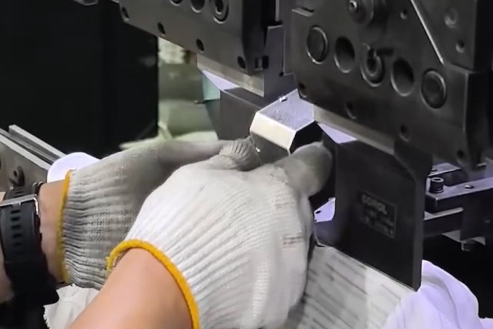
4. Tooling Makes or Breaks the Angle
Punch radius, V-die opening, die wear, crowning, ram deflection, and tool alignment all show up in the part.
A worn die can make a skilled operator look bad. A mismatched punch can create the wrong radius even if the angle looks acceptable. A long part can bend differently at the ends than in the middle if crowning is not set correctly.
The best shops treat tooling like part of the process spec, not background equipment.
5. Springback Is Always Waiting
Springback is the material trying to return toward its original shape after the forming load is removed.
Higher-strength materials usually spring back more. Larger radius-to-thickness ratios usually spring back more. Wider die openings can increase springback in air bending. Material lot changes can move the result even when the program stays the same.
That is why “just overbend it a little” is not a process plan. It is a guess.
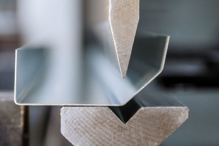
Air Bending vs Bottom Bending vs Coining
The bending method determines how much control you have over the angle and how much flexibility you keep on the floor.
A 2025 technical comparison from Komaspec’s air bending and bottom bending guide lists air bending around ±1° and bottom bending around ±0.5°, with air bending faster and more adaptable, but more variable. (Komaspec)
| Method | What Happens | Typical Strength | Common Risk | Best Use |
|---|---|---|---|---|
| Air bending | Punch pushes the sheet partly into the V-die without bottoming out | Flexible, fast, lower force | More springback and angle variation | Prototypes, lower-volume parts, many angle changes |
| Bottom bending | Material is pressed down into the die | Better angle repeatability | More tooling dependency, higher load | Repeated parts with tighter bend control |
| Coining | Material is heavily compressed into the die | Strong angle control | High tonnage, more tool marking, less flexible | Thin material, very tight control, special forming needs |
Here is the practical shop-floor version:
If you need flexibility, air bend.
If you need repeatability, consider bottoming.
If you need the angle locked down and can tolerate force, marking, and tooling cost, coining may be on the table.
But do not pick the method after the quote is approved. Pick it while the part is being designed.
Bend Radius and Thickness Ratio: Do Not Fight Physics
The relationship between inside radius and material thickness changes how the part forms.
A radius near material thickness is usually manageable for many common materials. A very tight radius can crack. A large radius can spring back more than expected because the material behaves less like a sharp fold and more like an elastic arc.
This is one reason radius callouts need to be realistic.
Bad callout: “R0.25 mm” on thick stainless because it looked clean in CAD.
Better callout: radius based on material grade, thickness, forming method, cosmetic needs, and available tooling.
For production sheet metal fabrication, we prefer to match the design radius to standard tooling whenever possible. Custom tooling can be worth it, but not for every bracket.
K-Factor and Bend Allowance: The Flat Pattern Is an Assumption Until Proven
The k-factor estimates where the neutral axis sits during bending. That neutral axis is the layer in the material that does not stretch or compress the way the outer and inner surfaces do.
In plain language: k-factor helps convert the 3D bent part into the correct flat blank.
The catch?
K-factor depends on material, thickness, radius, tooling, and bending method. So a value that worked on 5052 aluminum may not work on 304 stainless. A value that worked with one V-die opening may not hold after a tooling change.
For one-off work, a good default may be enough.
For production, we want proof. That means bend coupons, first-article inspection, and recorded bend deductions by material and tooling setup.
A shop that stores those offsets is not being fussy. It is building process memory.
A Better Process for Avoiding Out-of-Spec Bends
Here is the control plan we would rather see than another round of rework.
Step 1: Lock the Material Spec
Do not just say “aluminum” or “steel.”
Call out grade, temper, thickness, finish condition, and any grain direction needs. If the material can be substituted, define what substitutions are allowed. Otherwise, a supplier may choose a technically similar material that bends differently.
Step 2: Use Bend Reliefs Where Geometry Gets Crowded
Tabs, slots, holes, and notches near a bend line can distort. Bend reliefs reduce tearing and local stress.
A bend relief is cheap in CAD.
It is expensive after cracking.
Step 3: Match the Radius to Real Tooling
Ask what tooling is available before forcing a nonstandard radius. Standard tooling reduces setup time, lowers risk, and makes repeat orders easier.
If the radius is function-driven, say so. If it is just cosmetic, say that too.
Step 4: Run a Bend Coupon or First Article
For tight jobs, form a test strip from the same material lot and thickness. Measure actual springback. Then adjust the press brake program before running the batch.
This is boring.
Boring is good.
Step 5: Measure the Right Feature
Do not measure a bend angle from a burr, warped edge, or flexible flange and call it truth.
Use a stable datum. Use a repeatable method. For high-volume work, fixtures and go/no-go gauges often beat hand tools because they remove interpretation.
Step 6: Record Offsets by Material and Tooling
If the job runs again, the shop should not start from zero.
Record the material lot, tooling, die opening, punch radius, machine, operator notes, actual angle, correction, and inspection result.
Modern manufacturing is pushing harder toward connected production. Deloitte’s 2025 smart manufacturing survey found average gains of 10%–20% in production output among respondents using smart manufacturing initiatives. Better bend data fits that same direction: less guessing, more repeatability. (Deloitte)
Out-of-Spec Bend Troubleshooting Table
| Symptom | Likely Cause | What to Check | Best Fix |
|---|---|---|---|
| Bend opens after forming | Springback | Material strength, radius/thickness ratio, die opening | Overbend using measured offsets; consider bottoming for tighter control |
| Outside radius cracks | Radius too tight or grain issue | Grain direction, material temper, punch radius | Increase inside radius, bend across grain, change temper |
| Flange length is wrong | Bend allowance or k-factor error | Flat pattern, bend deduction, material thickness | Update bend deduction from test coupons |
| Angle varies along a long bend | Deflection or poor crowning | Ram crowning, tooling wear, die alignment | Adjust crowning; inspect tooling |
| First part good, later parts drift | Heat, setup movement, operator adjustment, batch variation | In-process inspection records | Add inspection frequency and program locks |
| Holes distort near bend | Feature too close to bend line | Hole-to-bend distance, relief geometry | Move feature or add bend relief |
| Cosmetic face marked | Tooling contact or dirty tooling | Punch/die condition, protective film | Use clean tooling, film, larger radius, or alternate method |
| Assembly does not fit though loose part passed | Stack-up error | Datums, mating parts, weld distortion | Inspect in fixture; review assembly tolerance chain |
Do Not Ignore Finishing and Assembly
A bend can pass inspection as a loose part and still fail in the real product.
Why?
Because bending is often only one step. Welding can pull angles. Hardware insertion can distort flanges. Powder coating adds thickness. Brushing can expose tool marks. Plating can make tight tabs tighter.
When a bent part is going into sheet metal assembly, the bend tolerance should be reviewed against the assembled condition, not just the single component.
The same goes for surface finishing. If the outside bend radius is cosmetic, protect it from tool marks. If the part will be coated, allow for coating buildup at mating edges. If the surface is brushed or grained, keep the visual direction consistent.
Bend accuracy is not only geometry. It is fit, function, and appearance.
Why This Matters More in 2026
The market is not getting more forgiving.
Global Market Insights’ 2026 sheet metal fabrication services market report estimates the market at USD 87.3 billion in 2025 and projects 4.6% CAGR from 2026 to 2035. More demand means more quoting pressure, tighter schedules, and less patience for avoidable rework. (Global Market Insights Inc.)
Automation is also raising expectations. The World Robotics 2025 report says 542,000 industrial robots were installed in 2024, with annual installations above 500,000 units for the fourth straight year. (IFR International Federation of Robotics)
That does not mean every bend needs a robot.
It does mean buyers expect repeatable process control. They expect better inspection records. They expect the second order to match the first.
Fair expectation.
Quick Checklist Before Releasing a Bent Sheet Metal Part
Use this before sending the file out for quote:
- Material grade and temper are specified.
- Thickness tolerance is understood.
- Bend angle and angular tolerance are defined.
- Inside radius is realistic for the material and tooling.
- Grain direction is called out when needed.
- Bend reliefs are added near slots, tabs, and corners.
- Hole-to-bend distances are manufacturable.
- Cosmetic side is identified.
- Finish requirements are clear.
- Inspection method is agreed.
- Assembly fit-up is considered.
- First-article approval is required for tight tolerance work.
A clean drawing will not solve every bend problem.
But a sloppy drawing almost guarantees one.
FAQ
What causes an out-of-spec angle bend in sheet metal?
The most common causes are springback, incorrect bend allowance, wrong tooling, material thickness variation, grain direction, poor radius selection, worn tooling, and unclear drawing tolerances.
How do you compensate for springback?
Measure it first. Then adjust the bend program, punch depth, tooling, or bend method. For repeat work, record springback offsets by material, thickness, radius, die opening, and machine setup.
Is air bending accurate enough?
Often, yes. Air bending is fast and flexible, especially for prototypes and moderate tolerances. For tighter angle control, bottom bending or coining may be better, depending on material, tooling, and cost.
Should bends go with or across the grain?
Across the grain is usually better when cracking risk matters. Bending with the grain can reduce forming force but may increase cracking on the outside radius, especially with harder materials or tight radii.
Why does my flat pattern look right but the formed part is wrong?
The k-factor, bend deduction, material thickness, or tooling assumption may be wrong. CAD defaults are not production proof. Validate with test bends and update the flat pattern using measured results.
Can finishing affect bend accuracy?
Yes. Coatings add thickness, brushing can expose marks, plating can tighten fits, and heat from downstream processes can affect assembled geometry. Finishing should be considered before the bend plan is locked.
The Shop-Floor Rule Worth Keeping
A good bend is not luck.
It is a controlled result: clear drawing, right material, realistic radius, matched tooling, measured springback, recorded offsets, and inspection that matches how the part will actually be used.
That is how you avoid an out-of-spec angle bend in sheet metal — not once, but across the full run.