


Sheet Metal Design Guidelines: Creating Sheet Metal Parts
sheet metal design looks simple up until the very first prototype comes back turned, oil-canned, distorted near the welds, or impossible to bend without fracturing.
We’ve seen it lots of times.
A bracket that functioned completely in CAD stops working at the press brake. A tidy room attracting needs 3 added setups since the bends fight each various other. An opening placed as well close to a bend turns oval. A powder-coated panel no more fits due to the fact that no one enabled covering density.
That is the actual factor of sheet metal layout guidelines: not making a prettier drawing, however making a part that can be cut, curved, constructed, ended up, examined, shipped, and mounted without drama.
Why Sheet Metal Layout Still Issues in 2026
The need side is not reducing.
Global Market Insights approximates the sheet metal fabrication services market at USD 91 billion in 2026, with growth projected via 2035. Grand Sight Study also reports that the wider sheet metal market is anticipated to grow at a 7.0% CAGR from 2025 to 2030.
That growth is not simply coming from one market. It is coming from enclosures, EV elements, automation frameworks, electronics housings, appliance panels, HVAC equipment, robotics, aerospace brackets, energy systems, medical carts, industrial closets, and custom-made machinery.
And purchasers are less patient than they made use of to be.
They want much faster quotes, cleaner models, smaller batches, even more modifications, and far better coatings. Deloitte’s 2026 production expectation likewise points to hefty financial investment in clever manufacturing, with manufacturers placing more spending plan into automation, sensing units, information, and production systems.
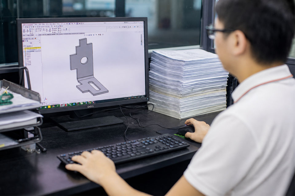
So of course, CAD issues.
But DFM matters more.
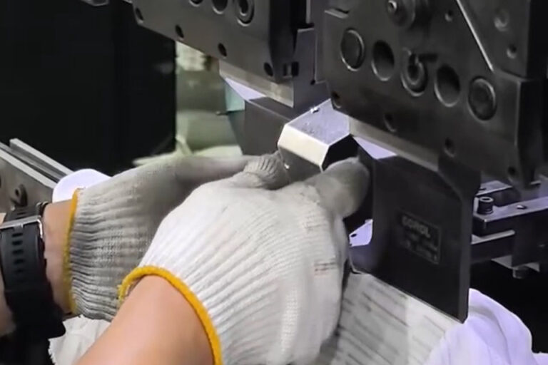
Begin With the Construction Technique
Prior to you consume over a radius or opening size, answer this very first:
How will the component really be made?
A one-off model, a 200-piece pilot run, and a 50,000-piece stamped component needs to not be developed similarly. The geometry could look similar, but the economics are entirely various.
For many sheet metal projects, the process mix consists of some version of cutting, forming, welding, equipment insertion, finishing, and assembly. A clever layout makes those steps simple.
A negative style makes each action suggest with the following one.
| Process | Best For | Keep an eye out for | Design Tip |
|---|---|---|---|
| Laser cutting | Models, low-to-mid volume parts, complicated flat patterns | Warmth marks, pierce factors, limited interior edges | Keep holes a minimum of product thickness where possible |
| Punching | Repeated holes, louvers, forms, tabs, production panels | Tooling limitations, minimum feature spacing | Reuse typical hole and port dimensions |
| Press brake flexing | Brackets, channels, covers, panels, enclosures | Bend sequence, device gain access to, short flanges | Keep bend distance regular |
| Marking | High-volume parts | Tooling cost, layout lock-in | Usage when quantity validates pass away financial investment |
| Welding | Frames, secured seams, hefty assemblies | Distortion, access, cleanup | Include gain access to and avoid heat-heavy joints near aesthetic faces |
| Hardware insertion | PEM nuts, studs, standoffs | Edge distance, material density | Confirm hardware specifications before launching illustrations |
| Completing | Aesthetic and corrosion-resistant parts | Finishing buildup, concealing, shade resistance | Design holes and fits with surface thickness in mind |
For production-ready sheet metal construction, the very best drawings are not one of the most complex drawings. They are the ones that get rid of uncertainty.
Material Option: Do Not Deal With Sheet Metal Like Generic metal
Material choice impacts bend distance, springback, toughness, coating, rust behavior, expense, and preparation.
That is a lengthy chain.
You can bend light weight aluminum, stainless-metal, cold rolled metal, galvanized metal, copper, and brass– but they do not behave the same way. Some spring back extra. Some fracture if curved also limited. Some are more challenging to weld easily. Some are great for powder covering. Others are better for plating, brushing, or plating.
Usual sheet metal Materials
| Product | Common Usage | Strengths | Design Care |
|---|---|---|---|
| Cold rolled metal | Braces, cabinets, covers, structures | Excellent strength, clean surface, cost-effective | Demands layer or plating for deterioration defense |
| Stainless metal | Food devices, medical, outdoor equipment | Corrosion resistance, tidy appearance | Greater springback, harder creating |
| Aluminum | Enclosures, panels, aerospace, electronic devices | Lightweight, deterioration immune, good coating choices | Softer, much more prone to scratches and nicking |
| Galvanized metal | HVAC, exterior panels, utility parts | Zinc finishing enhances rust resistance | Welding and completing need added planning |
| Copper | Electrical components, bus bars, decorative components | Conductivity, formability | Softer and more expensive |
| Brass | Ornamental equipment, electric get in touches with | Good look, deterioration resistance | Material expense and schedule can vary |
Make use of the same product thickness throughout the part unless there is a strong factor not to.
Mixing thicknesses in one design typically includes joining work, fixturing, evaluation steps, and expense. It can be done. Yet it should be a selection, not a crash.
Sheet Metal Density and Gauge: Choose Early, After That Layout Around It
sheet metal thickness manages virtually everything:
- Minimum bend span
- Minimum hole dimension
- Flange size
- Slot width
- Notch size
- Hardware compatibility
- Weight
- Rigidness
- Expense
- Creating threat
Assess graphes can aid, however do not rely upon gauge alone. Scale worths differ by product type. A 16-gauge metal sheet is not the very same thickness as 16-gauge light weight aluminum.
Usage decimal inches or millimeters on engineering drawings.
Better yet, consist of both if your distributor base is international.
sheet metal Tolerances: Limited Is Not Constantly Much better
This is where numerous layouts get pricey for no excellent factor.
A resistance should shield feature. That is it.
If a laser-cut cover just requires to sit over a frame, do not call out aerospace-level monotony. If a bracket opening simply clears an M6 screw, do not treat it like a bearing bore. Every unneeded limited resistance includes evaluation time, scrap danger, setup job, or revamp.
Practical Tolerance Starting Points
These are general design referrals only. Your maker’s equipment, tooling, material, and evaluation strategy always win.
| Function Type | Common Beginning Point | Notes |
|---|---|---|
| Laser-cut profile | ± 0.10– 0.25 mm | Depend upon material, thickness, device problem |
| Opening size | ± 0.10– 0.20 mm | Smaller openings and thicker sheets require extra care |
| Bend angle | ± 0.5 ° | — 1.0 ° Springback and product set variant matter |
| Bend-to-hole | ± 0.25– 0.50 mm | Hole location can change after forming |
| Overall developed dimension | ± 0.50 mm or more | Much more flexes typically indicates even more resistance stackup |
| Equipment location | ± 0.25– 0.50 mm | Validate with equipment vendor and insertion process |
| Bonded assembly | Project-specific | Warm distortion can dominate the tolerance strategy |
A good guideline: use tight tolerances just to attributes that manage in shape, function, security, sealing, placement, or appearance.
Whatever else needs to breathe a little.
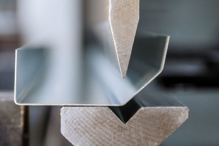
Bend Radius: The Policy That Conserves Parts From Splitting
A bend is not a sharp corner. It is a created distance.
That sounds evident, however CAD versions still reveal sharp bends constantly.
For most sheet metal parts, the within bend radius need to be at least equivalent to the product thickness. Some softer products can handle tighter distances. Some harder products need more room. Stainless metal and high-strength alloys usually penalize aggressive bend distance.
For sheet metal flexing, keep these guidelines in mind:
- Make use of a constant inside bend distance throughout the component.
- Stay clear of very short flanges.
- Keep openings and ports away from bend lines.
- Add bend relief where sides would tear.
- Straighten bends in the same direction when functional.
- Prevent deep U-shapes that restrict tool gain access to.
- Confirm whether the part is air bent, bottomed, or created.
Minimum Flange Size
A flange that is as well brief might not rest effectively on the press brake tooling.
As a rough starting point, the minimal flange size should normally be at the very least 4 times material density, though tooling and bend distance can push that higher.
Small flanges look harmless in CAD.
On the production line, they can be irritating.
Bend Allocation, K-Factor, and Apartment Patterns
The flat pattern is not simply the folded version squashed with a button.
When sheet metal bends, the within the bend presses and the outdoors stretches. The neutral axis changes depending on product, density, bend radius, and forming technique.
That is where bend allowance, bend reduction, and K-factor been available in.
If your level pattern is incorrect, the completed component will be incorrect.
Most CAD systems can calculate this, but the setups need to match the fabricator’s process. Do not presume the default K-factor is excellent sufficient for production.
Ask your producer for:
- Preferred K-factor or bend reduction table
- Standard tooling distance
- Minimum flange size
- Air bend information
- Material-specific bend rules
- Preferred grain instructions
That 10-minute discussion can save a full prototype cycle.
Openings and Ports: Maintain Them Away From Problem
Openings as well close to bends flaw.
Slots also near sides tear.
Countersinks in slim sheet fall short.
Hardware holes as well close to sides bulge, distort, or pull out.
Make use of these beginning regulations:
| Attribute | Recommended Standard |
|---|---|
| Minimum round hole size | At least 1x material density |
| Stainless or harder alloys | Usually 2x product density is more secure |
| Hole-to-edge range | At least 2x material thickness |
| Hole-to-hole range | 2– 3x product density |
| Hole-to-bend range | At the very least 2.5 x material density + bend distance |
| Port size | A minimum of 1x product thickness |
| Notch size | A minimum of 1x material density or 1 mm, whichever is greater |
| Countersink depth | Prevent surpassing concerning 60% of product density |
A small change in opening positioning can make a big difference.
Relocate the hole. Save the part.
Notches, Tabs, and Bend Alleviation
Notches and tabs are useful, yet they need proportion.
A notch that is also slim creates tension concentration. A tab that is also long bends or spins. A bend alleviation that is missing can trigger tearing beside the bend.
Usage relief cuts when a bend finishes near an edge, flange, notch, or surrounding bend.
A common starting point:
- Relief width: at the very least material thickness
- Alleviation deepness: bend radius + product density
- Interior edge span: a minimum of 0.5 x product thickness
Stay clear of sharp internal edges where stress and anxiety will collect. Spherical edges are usually much better for tiredness, developing, coating, and handling.
Hems, Curls, Ribs, Louvers, and Embossments
These attributes can make a part stronger, much safer, better-looking, and easier to handle.
They can also force custom tooling.
Hems
A hem folds the edge back onto itself. It eliminates sharp sides and increases rigidity.
Usage open hems or teardrop hems when cracking is an issue. Level hems can work in some materials, yet they are not constantly friendly to layered, fragile, or more challenging sheet.
Curls
A crinkle rolls the edge into a rounded kind. It enhances edge safety and rigidity.
Keep crinkle distance generous. A great beginning point is an outdoors span around 2x material density.
Ribs and Embossments
Ribs include tightness without including density.
That is useful for panels, covers, and wide faces that may flex or oil-can. However ribs require spacing, tooling, and creating clearance. Do not spray them right into the design even if they look technological.
Louvers and Lances
Louvers are common in ventilation panels and units.
They normally require tooling. Maintain dimension, spacing, and direction constant. Likewise think about air movement, water entry, powder finishing coverage, and cleansing accessibility.
Hardware: Design Around the Bolt Prior To the Drawing Is Done
Threaded inserts, studs, standoffs, rivet nuts, and PEM-style equipment prevail in sheet metal. They are likewise easy to abuse.
Before positioning hardware, confirm:
- Minimum sheet density
- Opening size
- Edge range
- Range in between bolts
- Installation pressure
- Gain access to for insertion tooling
- Plating or finish limitations
- Pull-out and torque-out requirements
Do not position a bolt also close to a bend.
And do not presume every fastener operates in every product. Aluminum, stainless-metal, and low-carbon metal usually require different equipment specifications.
If the part comes to be a welded or fastened subassembly, strategy sheet metal setting up while the layout is still versatile– not after every hole is frozen.
Welding and Signing Up With: Warm Changes the Part
Welding is not just a line on an illustration.
It adds warm, contraction, distortion, cleaning, discoloration, and assessment demands.
For sheet metal, the large dangers are:
- Deformed panels
- Burn-through on slim product
- Aesthetic heat marks
- Poor torch access
- Excessive grinding
- Misalignment from weld shrinking
- Layer issues near bonded joints
Design ideas:
- Use tabs, slots, and situating attributes for positioning.
- Avoid long continuous welds unless required.
- Use sew welds where strength and securing allow.
- Keep welds away from cosmetic faces when feasible.
- Add accessibility for the welding torch and fixture.
- Strategy finishing after welding.
If you require a sealed unit, say so early. If you only require toughness, do not over-specify weld length.
Surface Area Finishing: Design for the Finish, Not Simply the metal
Ending up is typically dealt with like the last step.
That is risky.
The coating can impact thickness, shade, corrosion resistance, masking, grounding, fit, strings, and aesthetic acceptance.
Typical choices include:
- Deburring
- Cleaning
- Grain blasting
- Powder covering
- Wet painting
- Anodizing
- Electroplating
- Passivation
- Zinc plating
- Black oxide
- Silk testing or marking
Plan surface finishing prior to final dimensions are secured.
Powder finishing, for example, includes density. Anodizing behaves in different ways on different aluminum qualities. Plating can build up in holes and threads. Brushed finishes need grain instructions control. Aesthetic panels may require special product packaging to avoid scratches.
Small detail?
Not when the client turns down the entire batch over look.
Creating Custom-made sheet metal Parts genuine Manufacturing
When you create personalized sheet metal parts, think beyond a solitary feature.
Think of the full path:
- Material purchase
- Cutting
- Deburring
- Developing
- Equipment insertion
- Welding or attachment
- Grinding or cleaning
- Ending up
- Examination
- Packaging
- Assembly
- Area installation
Every action can change the component.
The far better your illustration prepares for that path, the less surprises you obtain.
Sheet Metal Style List
Utilize this before launching a drawing.
Geometry
- Are all bends possible with basic tooling?
- Are bends facing the exact same instructions where practical?
- Are flanges long enough?
- Are bend alleviations included where required?
- Are inside corners radiused?
- Are huge flat panels stiff enough?
Holes and Attributes
- Are openings at least product thickness?
- Are holes much enough from bends?
- Are slots large enough?
- Are countersinks reasonable for the sheet thickness?
- Are notches and tabs proportioned appropriately?
- Are louvers, ribs, and embossments suitable with tooling?
Material
- Is the product grade defined?
- Is thickness received mm or decimal inches?
- Is grain instructions important?
- Is the product ideal for the bend distance?
- Is corrosion resistance addressed?
Resistances
- Are limited resistances restricted to useful features?
- Is monotony sensible?
- Is resistance stackup reviewed?
- Are assessment factors clear?
Setting up
- Are fasteners defined?
- Is hardware suitable with sheet thickness?
- Is tool gain access to offered?
- Are weld icons clear?
- Are mating parts examined?
End up
- Is the surface defined plainly?
- Are aesthetic faces identified?
- Are threaded locations covered up if required?
- Is layer accumulation enabled?
- Is product packaging specified for aesthetic components?
Typical Sheet Metal Style Mistakes
Mistake 1: Creating Sharp Interior Corners
Sharp edges boost tension and are tougher to cut cleanly. Usage span.
Mistake 2: Placing Holes Too Close to Bends
The opening will certainly misshape throughout creating. Relocate away or add alleviation.
Mistake 3: Calling Out Limited Resistances Anywhere
This increases cost and evaluation time. Tighten up only what matters.
Mistake 4: Failing To Remember End Up Thickness
A coated tab might no longer fit into a slot. A layered opening may no more clear a bolt.
Mistake 5: Disregarding Bend Sequence
Some components can be designed yet not bent in the order needed. Press brake access issues.
Mistake 6: Choosing Product Too Late
Material affects springback, bend radius, coating, price, and availability.
Error 7: Avoiding Fabricator Testimonial
The earlier a fabricator evaluates the layout, the simpler it is to deal with problems cheaply.
FREQUENTLY ASKED QUESTION: Sheet Metal Layout Guidelines
What is the most effective bend span for sheet metal?
A good starting factor is an inside bend radius equal to the product density. Softer materials might permit tighter bends, while stainless metal and more difficult alloys usually need a larger span.
Exactly how close can a hole be to a bend in sheet metal?
A typical guideline is to maintain the opening at least 2.5 times the product thickness plus the bend span far from the bend line. Extra range is safer when appearance or limited fit issues.
What is the minimal hole dimension for sheet metal?
For several sheet metal parts, the minimum hole size need to go to the very least equal to the material density. For stainless metal or tougher materials, 2 times material thickness is often a much safer starting factor.
What tolerance should I make use of for sheet metal parts?
Use the loosest tolerance that still safeguards fit and feature. Laser-cut functions might hold tighter dimensions than formed or bonded settings up, yet every bend and weld adds variation.
Which product is best for sheet metal parts?
It depends upon the work. Cold rolled metal is cost-effective and solid, stainless-metal resists rust, light weight aluminum saves weight, and galvanized metal functions well for many outdoor or heating and cooling applications.
Should sheet metal parts be designed before choosing a surface?
No. Pick the finish early. Powder finish, plating, anodizing, brushing, and passivation can all influence measurements, appearance, concealing, and cost.
When should I involve a sheet metal producer?
Prior to last drawing launch. A producer can assess bend distances, tooling access, material option, resistances, equipment, welding, and finishing prior to blunders become pricey.
A Better Method to Style Sheet Metal Parts
Great sheet metal style is not about packing every regulation right into one drawing.
It has to do with making tradeoffs with your eyes open.
You desire adequate stamina, enough precision, adequate surface quality, and enough repeatability– without adding attributes, resistances, welds, or tooling that the component does not need.
That is the distinction in between a component that merely looks right in CAD and a part that operates in manufacturing.